Notes on Marlin – Auto Bed Levelling

Upon enabling the auto bed levelling feature of the Marlin firmware I learned a thing or two through trial and error and wished it had been better documented so I’ll try and let you know what I’ve learned.

Here are links to some useful information that all helped me get setup:

Firmware setup
Hardware setup
PrintrBoard setup

In the Marlin firmware, where you set the left, right, back and front positions for probing, do not set the left and front positions below 10.  I tried 5 (assuming the bigger the test area the better results you would get) and wondered why moving the nozzle back to X0 Y0 after homing resulted in the nozzle crashing both X & Y in to the min endstops.  I quickly noticed that at the start of the probing both the nozzle did not move in either X or Y so they were both then 5mm out when homing after the probing.  I now use 20 for left and front.

I also found that if you just move X & Y to home before probing and your nozzle is quite high in relation to the bed then the bed probe would stop way before it even touched the bed.  I thought I’d fix this by homing the Z before probing but you need to make sure that the probe is within your bed probing co-ordinates (i.e. the middle of the bed, or at least more than you’ve set for left and front).

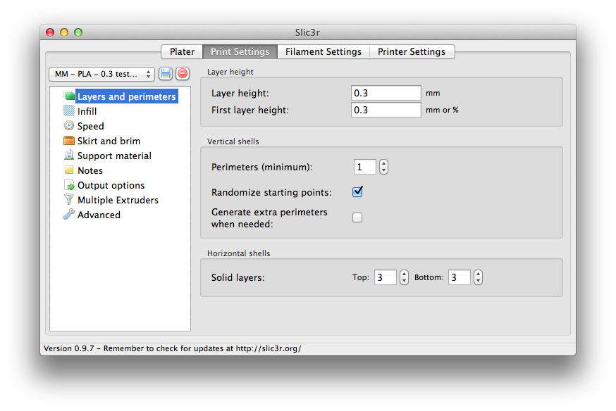
So here is my start G-Code* that I’ve put in to Slic3r:

G28 X0 Y0 ;home X & Y
G1 X100 Y100 F5000 ;move nozzle to centre of bed
G28 Z0 ;home Z
G29 ;probe bed
G90; set absolute coordinates
G92 E0; reset extruder distance
G1 Z5 F300 ;move nozzle up 5mm for safe homing
G1 X0 Y0 Z0 F5000; move nozzle to home

*If you’re going to use this code then please set your own bed centre and move velocities appropriate to your printer.

If I discover anything more on this topic then I’ll update this post.

Tagged , ,

Marlin – Auto Bed Levelling

A great feature was added to the Marlin firmware last year and I’ve finally gotten round to implementing it on my printer.

There were quite a few hurdles to over-come including designing some new parts to make it work.

I wanted to re-design the whole X – axis for my Mendel-Max as the clamps for holding the X – axis rods were poor and the belt being outside of the 2 rods meant there was a considerable amount of turning force on the parts, especially if you wanted tight belts.

So with the belt now between the 2 rods I had to completely re-design the carriage not only because the belt clamps had to be moved but I wanted to move to a direct-drive extruder on top of designing the probe arm to probe the bed!

With all of the new designs complete there were plenty of adjustments to be made to the firmware.  Moving to a direct-drive extruder meant new E – step / acceleration / speed settings. Enabling the bed levelling, setting up the servo including finding out which pin to assign to the servo for my PrintrBoard.  The biggest hurdle was discovering that by enabling the bed levelling filled the RAM on the PrintrBoard! To make the firmware fit I had to remove parts of the LCD menu.

After you have everything is working you need to set the distance from the hot-end to the micro-switch on your probe arm. Spend some time getting this as accurate as possible makes for the best result and only needs to be done once.

Has it been worth it? YES!

It’s great not having to adjust the bed manually, you can fine tune the distance between the nozzle and the bed in the LCD menu which is far more stable that any screw adjustments.

Tagged , , ,

Slic3r 1.0.0 RC3

So Slic3r is almost at an official version 1!!

The latest release is less about features and more about but fixes.

As always, a very big thank you goes out to Alessandro Ranellucci and everyone else who has contributed to the application.  Especially in keeping it FREE!

The ONE bug I hope gets fixed before the final version 1 gets released is hole diameters.

It’s quite well documented on the Slic3r forums that the holes generated by Slic3r are smaller than designed.  Fingers crossed for version 1.

Tagged ,

Slic3r v1.0.0 RC1

Slic3r keeps on maturing and getting better with each revision.  Their current release, version 1 release candidate 1 has some great new features.

You can check out the full release notes and download your own copy HERE

A few major changes are:

  • built-in automatic STL repair
  • new support material rewritten from scratch
  • options to avoid starting loops on convex vertices and/or overhangs
  • improved infill patterns and bridge detection

I have already found the STL repair to be very good and saves me a trip round NetFabb and the new infill fills in small holes much better (I always use small gear from Greg’s Wade reloaded Extruder to test whether the infill works or not).

The previous Slic3r (version 0.9.10b) below:

Slic3r Old

.

.

.

.

.

.

The latest Slic3r (version 1.0.0 RC1) below:

Slic3r New

.

.

.

.

.

.

I used to get round this by adjusting the Advanced settings but now Slic3r does it all automatically 🙂 JOY!

Hot-End & Bed Calibration

In the quest to fine tune our printers I found a very good guide on how to calibrate the PID control of the Hot-End and the Heated Bed.

If you find that your hot-end temperature fluctuates more than you’d like it to or that it over-shoots or stops short of the set temperature then this is for you.

Again, the source of this information comes from Lincomatic but this time there was a great summary found HERE

The Process:

  1. Allow your hot end to cool to room temperature
  2. In Pronterface or Repetier, send the command: M303 Snnn (where nnn = the temperature you’re extruding at, eg 230 for ABS would be M303 S230)
  3. Wait whilst the printer ramps up and down the hot-end temperature
  4. Input results into your Firmware

The results you get back will look something like this:

bias: 101 d: 101 min: 145.48 max: 154.02
Ku: 64.06 Tu: 29.67
Clasic PID
Kp: 38.04
Ki: 2.35
Kd: 147.63

Input the last 3 sets of numbers into your firmware here:

#define DEFAULT_Kp 38.04
#define DEFAULT_Ki 2.35
#define DEFAULT_Kd 147.63

You can also do the same for the heated bed by using M303 E-1 Snnn (where nnn is the temperature you normally run the bed at, eg M303 E-1 S60)

Tagged ,

Extrusion Calibration v2

After re-reading Triffid Hunter’s calibration guide I was specifically curious about the final comments about volumetric extrusion which makes sense as we are dealing with something that has volume.

You can read up on the process and the rationale behind it HERE

Put simply:

  1. Set the filament diameter to 1.128379 and never change it
  2. Set the extrusion multiplier to 1 and never change it
  3. Divide your E-Steps by 7 for 3mm filament or 2.4 for 1.75mm filament
  4. Multiply your E related speeds, accelerations and retractions by 7 for 3mm filament or 2.4 for 1.75mm filament
  5. In Sli3r multiply the Retraction Length and Retraction Speed by 7 for 3mm filament or 2.4 for 1.75mm filament

Multiply the E settings by 7 for 3mm filament or 2.4 for 1.75mm filament in the Marlin firmware in the following lines:

Configuration.h

#define DEFAULT_AXIS_STEPS_PER_UNIT
#define DEFAULT_MAX_FEEDRATE
#define DEFAULT_MAX_ACCELERATION

#define DEFAULT_ACCELERATION
#define DEFAULT_RETRACT_ACCELERATION

The only calibration you will then make is by altering the E-Steps.  You can alter this mid-print by either sending gcode M92 Ennn (where nnn = the new E-Steps number) or by adjusting it on the printer’s LCD control panel.

You can either calibrate the E-Steps by visual inspection where you’re looking for gaps in the infill at 95% and with no gaps on a solid fill or after slicing a single wall cube with no infill look in the gcode for the perimeter width, print it halfway and then measure the wall width.


Tagged ,

LCD and Encoder controls (Panelolu) – – – – – – – Part 2, Hardware

This is the hardware section of installing a Panelolu control panel to your PrintrBoard based 3D printer. Please refer to ​part 1, Software post for the updates you need to make to your firmware necessary to prepare your PrintrBoard for the Panelolu.

Again, thanks go to think3dprint3d​ for the following info. More details are available there. Please let me know if you need any further information regarding anything posted here.

The plugs and pins for the LCD and PCB come supplied with the Panelolu kit however for the connections to the PrintrBoard I recommend purchasing two 14 pin connectors similar to connectors found HERE​. I used the 2×7 so I can make further connections in the future. You will also need to buy the pins sold separately.

Notes:

The numbers represent the wire number of the ribbon cable. 1 & 2 were left out for possible connections to Ground and +12Vdc for any future additions to the Panelolu box.

The ‘grey’ 3 is ground and the ‘red’ 4 is +5Vdc. The multiple 3s and 4s must be connected together.

​The ‘yellow’ B and ‘green’ C are the Brightness and Contrast inter-connections between the LCD & PCB.

PrintrBoard Expansion Ports

PrintrBoard Expansion Ports


These are the headers to where you need to connect to on the PrintrBoard.


PrintrBoard Connections

PrintrBoard Connections


​      This is a simplified sketch of the connections to the PrintrBoard.


LCD Connections (rear)

LCD Connections (rear)


These are the connections to the rear of the LCD.  Note the right to left numbering of the pins.


Panelolu PCB Connections

Panelolu PCB Connections

Finally, these are the connections to the Panelolu PCB.

PrintB.it

I have decided to branch out and create a new website with which I can provide more information regarding the designs I’ve made for my printer and also sell some parts that I’ve been able to source.

Come have a look : www.printb.it

PrintBit Logo 1sq

Extruder Calibration – [UPDATE]

Until recently I had not found a method of calibrating the amount of extrusion required for a good print which has worked well for me.

Well…. All that has change since I stumbled upon this post: HERE

Of course I calibrate the extruder stepper like most people do (see Slic3r is Nicer) but I still had to fudge around with the Filament Settings / Extrusion Multiplier and the Printer Settings / Advanced to get something that resembled a ‘nice’ print.

I would change the Advanced settings from their default, print something and then change again and again until the print looked right as I had never found a good guide for setting up Slic3r.

[UPDATE:

Since I’ve been using this technique for a few weeks I wish to share what extra bits I’ve learnt.

When Calibrating make sure you set the extruder to slow down when print time is below 0 sec.  I found it difficult to get a good calibration when the walls were made with a slow moving head so this makes sure the head DOES NOT slow down.

Set First Layer to 200% for good adhesion.

Set Infill to 125% to fill in any gaps in the top layer.]

So, from the “Solidoodle Tips” post I know that the Default Extrusion Width should be 1.4 times the layer height (eg. Layer height = 0.3 then Extrusion Width = 0.42) (0.2 = 0.28)

To then calibrate the extrusion:

  • Create or change your settings in Slic3r to use for this test:

Layer Settings: (click the picture for a larger version)

Layer Settings

Infill:

Infill

Advanced:

Advanced

Filament Settings: (obviously don’t copy my Diameter or temperature settings, just the Extrusion Multiplier)

Filament 1

  • Download / design a small (eg. 20 x 20 x 20mm or try this) cube.  Print with the settings as shown above.  We are trying to print a wall which is a single line of filament thick so minimum perimeters is set to 1 and Fill Density (infill) set to zero.  This will give us a single wall hollow cube.  Stop the print when it has printed halfway up the cube as we want to measure the thickness of the wall.
  • Measure actual printed wall thickness will digital callipers.
  • If you’ve printed at 0.3mm layer height this SHOULD read 0.42mm (the width you’ve told Slic3r to print).
  • If not (mine printed 0.55mm!!) then divide what it should be by what you’ve measured.  0.42 / 0.55 = 0.7636363636 for example
  • Copy and paste the total into the Extrusion Multiplier: (I rounded the number)

Filament 2

Print the cube again and re-measure.  If it’s still not quite right then divide the Extrusion Multiplier by the measured thickness, then times by what it should be.  (0.7636363636 / 0.44) * 0.42 = 0.72892561983471 for example.

I know this isn’t that straight forward but I wish I had found this method a long time ago!  Thanks go to Ian Johnson over at Solidoodle Tips, he’s got a great website there full of VERY useful information to help you with your prints.

Hope this helps, let me know if it does or if you’d like any further information. Thanks.

LCD and Encoder controls (Panelolu) – – – – – – – Part 1, Software

I’d like to first thank the people over at think3dprint3d.com for all the hard work they’ve done in providing most of the work in connecting an LCD and encoder to the PrintrBoard. I’m re-posting this information using the code that works for my PrintrBoard I use on my MendelMax. If this helps you with your machine then please leave a comment.

This code should work with any PrintrBoard connected to either a MendelMax, Printrbot or any 3D printer where you’re using Marlin firmware.

This post has 2 parts, this, the Software part and part 2, the Hardware part which will show the wiring diagrams for the LCD and controls.

The examples given will be using the latest version (at the time of writing) of the Marlin firmware.  Download it HERE

You must first prepare the files Configuration.h and pins.h within the firmware to access the LCD and encoder.

Configuration.h

line 48-50

#ifndef MOTHERBOARD
  #define MOTHERBOARD 81
#endif

line 78-81

#define TEMP_SENSOR_0 1
#define TEMP_SENSOR_1 -1
#define TEMP_SENSOR_2 -1
#define TEMP_SENSOR_BED 1

line 216-218

const bool X_ENDSTOPS_INVERTING = false; //set to true to invert the logic of the endstops
const bool Y_ENDSTOPS_INVERTING = false; //set to true to invert the logic of the endstops
const bool Z_ENDSTOPS_INVERTING = false; //set to true to invert the logic of the endstops

line 275 – Obviously change these values to your own printers configuration.

#define DEFAULT_AXIS_STEPS_PER_UNIT   {78.7402,78.7402,200*8/3,760*1.1}

line 279-283 – Not necessary but I like to slow down the acceleration for less ringing when changing direction.

#define DEFAULT_ACCELERATION 1500 //X, Y, Z and E max acceleration in mm/s^2 for printing moves
#define DEFAULT_RETRACT_ACCELERATION 3000 //X, Y, Z and E max acceleration in mm/s^2 for r retracts
#define DEFAULT_XYJERK 12.0

line 302-307

//LCD and SD support
//#define ULTRA_LCD //general lcd support, also 16x2
#define SDSUPPORT // Enable SD Card Support in Hardware Console
#define ULTIMAKERCONTROLLER //as available from the ultimaker online store.
//#define ULTIPANEL //the ultipanel as on thingiverse
pins.h

line 961

#define FAN_PIN            22  // Fan

line 973 – To enable SD card support you must move the Y-endstop to the E-endstop pins (see previous post)

#define Y_STOP_PIN         37

line 989-994

#ifndef SDSUPPORT
  // these pins are defined in the SD library if building with SD support
    #define SCK_PIN          21  // 9
    #define MISO_PIN         22  //11
    #define MOSI_PIN         23  //10
  #endif

line 995 add the following

#ifdef ULTRA_LCD
 #ifdef NEWPANEL
  //we have no buzzer installed
  #define BEEPER -1
  //LCD Pins
  #define LCD_PINS_RS        41
  #define LCD_PINS_ENABLE    1
  #define LCD_PINS_D4        11
  #define LCD_PINS_D5        9
  #define LCD_PINS_D6        6
  #define LCD_PINS_D7        4

  //The encoder and click button
  #define BTN_EN1 2  //must be a hardware interrupt pin
  #define BTN_EN2 3  //must be hardware interrupt pin
  #define BTN_ENC 0  //the click

  //not connected to a pin currently
  #define SDCARDDETECT -1

  //from the same bit in the RAMPS Newpanel define
  //encoder rotation values
  #define encrot0 0
  #define encrot1 2
  #define encrot2 3
  #define encrot3 1

  #define BLEN_C 2
  #define BLEN_B 1
  #define BLEN_A 0
 #endif //Newpanel
#endif //ULTRA_LCD

Upload this firmware to your PrintrBoard (how-to).

Once updated restart your PrintrBoard. If you have the LCD connected then it should display data about your printer. If you haven’t connected the LCD to your PrintrBoard yet then it’s worth attempting to connect your computer to the PrintrBoard to make sure everything is still working correctly.

Tagged , , , ,